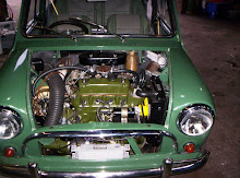
Let's get the yellow hose to the snorkel. It connects the valve with the ThermAC ThermAC switch. The valve is used during a cold start to the fact that as soon as possible to the engine block pre-heated by air drawn in is to rapidly provide proper exhaust emissions. How the switch works exactly, I do not know, but I think it can, depending on the temperature (should be a bi-metal switch) be something of the pressure valve in the snorkel through to fill this order - if necessary. The switch should operate in both directions, Wierum the hoses are connected not have to worry. (If not please contradict! Bin as well versed soo not.)
ThermAC switch from the red hose goes to the intake manifold. (Photos from the engine coming soon. As long as simply hope that the old bottles are still there to hinzuhangeln around.)
From there is the short hose (in black / white) for connection to the gas trap. The petrol is the case, held by a bracket on the fire wall (separation between the engine and passenger compartment) to the left / behind the air box. Remove the Lufi best, makes it easier to work a lot easier.
The connections are designed so that a "reversed polarity" is almost impossible (but "is not" is not, therefore, to note that the management ECU ran to the green connector to be! ). The long, green-coded cable leads for connection to the underside of the ECU next to the connector of the engine wiring harness.
Saturday, 17 April 2010
The "hierarchy"
Sunday, 18 October 2009
Jacking the Car
Three different types of jack are used on the range of models. First, there is the screw-type, which fits into a socket approxi¬mately at the mid-point of the body sill, allowing each side of the car to be lifted with the front and rear wheels clear of the ground. Some of the earlier jacks caused alarm and despondency by buckling as soon as a load was placed on them but the sturdier replacements should not give trouble, provided that the jacking bar is inserted fully into the bracket. If this is not done the jack will be damaged and the bracket distorted.
If the sealing plug has been lost, it may be necessary to clear any accumulation of mud or grit from the socket to allow the projection on the jack to be pushed fully home. Fit a new plug at the first opportunity. If water is found on the floor of the car after driving in wet weather, make sure that one of the rubber plugs is not missing. The water can find its way into the hollow body sill and from there into the car.
The jack should lean outwards slightly at the top to allow for the tilting of the car as it is raised. To allow the central screw to be turned by the wheel-brace, it will be necessary to leave the door of the car open, which can be decidedly unpleasant for passengers in cold or wet weather. More-over the open door can, on occasion, constitute a very real traffic risk. These drawbacks may prompt some owners to carry a conventional screw-type or hydraulic jack which can be applied beneath the normal jacking point.
Never be tempted to jack at any other point, owing to the risk of damaging a body member or the underframe. Also, the situation does arise sometimes in which the desired wheel fails to leave the ground when the jack is fully extended. This calls for some redistribution of the weight in the car which will, of course, tend to pivot around the central jacking point!
Two other tips: make sure that the handbrake is fully applied and that the car is on firm, level ground. If the wheel that is to be removed is next to the kerb, make sure that there will be sufficient space to allow it to be drawn off its studs when it has been jacked-up.
When a ratchet jack is provided, a levelling bracket must be fitted to the pad on the jack, before jacking up the front wheels. The flanges of the bracket must be uppermost and its slot located over the tongue of the pad.

1. Brake drum
2. Steering swivel
3. Upper suspension arm
4. Suspension unit
5. Clutch operating lever
6. Starter solenoid switch
7. Heater water tap
8. Oil filler cap
9. Ignition coil
10. Vacuum ignition-control vapour trap
11. Radiator filler cap
12. Cooling fan
13. Dynamo or generator
14. Fan and dynamo driving belt
15. Radiator drain tap
16. Universal joint
17. Lower suspension arm
18. Transmission casing (engine sump) drain plug
19. Starter motor
20. Oil filter
Place the jack under the front crossmember on the side on which the wheel is to be lifted, as close as possible to the front flange. When a rear wheel is to be raised, the levelling bracket is not needed. Instead, the tongue of the jack must be engaged with the socket on the rear face of- the crossmember.
The third form of jack is the type in which the jacking arm is pivoted on a strut and is moved forward by turning a ratchet handle. First raise the head of the jack until it is in contact with the front or rear crossmember, on the side on which the wheel is to be raised, with the tongue of the jacking pad behind the front crossmember or engaged with the socket provided on the rear face of the rear crossmember, as the case may be. The pad can be raised quickly into position by rotating the milled nut on the end of the jacking screw. Fit the ratchet handle with the word "Raise" outwards and operate it to lift the wheel. To lower the wheel, take off the ratchet handle and reverse it so that the word "Lower" faces outwards.
Fig. 1. How it all began. An early Mini undergoing extensive tyre tests with the Dunlop test team. The operator is measuring the temperature of the front tyre treads after a spell of fast driving
It has been the experience of car manufacturers that a large proportion of drivers in the "family car" class neither require nor appreciate a full set of instruments. Consequently, on the less-expensive models the instruments have been reduced to two essentials, the speedometer and the fuel gauge. A green warning light ensures that any failure of the engine lubrication system will not be overlooked, and a red warning light similarly draws attention to failure of the dynamo to charge the battery and also reminds a forgetful owner not to leave the ignition switched on when the engine is not running. The functions of both these important warning lights will be discussed in more detail later. An owner who likes to have a more comprehensive set of instruments will be interested in the special instrument panels obtainable from accessory shops or the neat Smith's instrument sub-panel which can be mounted beneath the lower edge of the facia panel and which will carry two instruments from the Smith's 2-in. range: for example an oil-pressuregauge, water-temperature gauge, an ammeter; or one of these gauges paired with a dual gauge (oil-pressure and water-temperature, for example) thus giving three additional gauges. Provision is also made on the panel for an electric cigarette lighter.Ignition and Charging Warning Light. The red warning light incorporated in the speedometer dial should glow as soon as the ignition is switched on and when the engine is idling but should fade out when the dynamo begins to charge as the engine is speeded-up. If it continues to glow at normal running speeds, check for a slack or broken dynamo driving belt, especially if the light comes on suddenly during a spell of fast driving. As the belt also drives the fan and water pump, the sudden lighting-up of the warning lamp can enable one to spot the trouble before overheating occurs.
The Missing Starting Handle
A retrograde feature of the Minis which they share with many other modern cars is the lack of a starting handle. Most do-it-yourself owners will regret the absence of this useful item when carrying out many servicing jobs. A starting-handle kit is available which can be fitted by any owner who has an electric drill and is able to handle simple tools. This conversion will be dealt with in a moment, but in the absence of a starting handle what is the best method of turning the engine?
When it is simply a matter of making adjustments, the best plan is to remove the sparking plugs in order to relieve the pistons of compression pressures and to turn the engine by pulling on the fan belt. An alternative scheme when a manual gearbox is fitted is to turn the steering wheel to full right lock, jack up the offside front wheel, engage top gear and rotate the engine by turning the road wheel. Some owners adopt this method, as a last resort, to start the engine when the battery charge is too low to turn the starter motor but sufficient current remains to operate the ignition system. In such a case a quick twirl of the front wheel, after switching on the ignition and setting the mixture control, will usually produce a start but do make sure that the handbrake is applied really firmly and that the jack is secure. If the car should topple off the jack after the engine has been started the results might be disastrous!
The starting-handle kit just referred to is made by Oselli Engineering, Industrial Estate, Stanton Harcourt Road, Eynsham, Oxon. It is ingeniously arranged so that the handle can be inserted when the left front wheel is turned to full lock. It is necessary to cut an opening in the wheel valance and to bolt two guide plates in place to position the inner end of the handle. A bracket, bolted to the front suspension, steadies the outer end of the shaft. The only other job to be done is to unscrew the crank shaft-pulley securing bolt and substitute the starting-handle dog bolt, which is also provided in the kit.
On later models on which the starter motor is controlled by the ignition key, through a solenoid (electro-magnetic) switch in the engine compartment, it is possible to use an ingenious device known as the ETT 80A Junior Autopoints Unit, which was obtainable at the time of writing from Eldred Motors and Electronics Ltd., 15a Lincoln Road, Hull, E. Yorks. When this is connected-up to the battery and starter solenoid switch, the engine can be "inched" round at the slowest possible speed, making precise adjustment an easy matter.
The device is not expensive and if you intend to carry out home maintenance as a regular rule, it will soon repay its cost, as it can also be used to set the basic ignition timing, check the actual firing point of the engine, check the condition of the starter ring gear and for other purposes which are described in the instruction leaflet which accompanies the unit.
Interior Heater

The earlier type of heater, fitted as standard on deluxe models and available as an optional extra on the remainder of the range, is of the simple recirculating type rudely termed a "fug-stirrer" in some quarters since it draws in and recirculates the air inside the car, instead of drawing in a fresh supply from outside. In hot weather the fan can be used for cooling purposes if the water supply to the heater is turned off by the tap at the hose connexion on the engine. Later heaters are of the fresh-air type and the tap is controlled from inside the car.
The fan motor will operate only when the engine is switched on. The initial movement of the switch brings the motor into operation at full speed. Further rotation reduces the speed (and the noise of operation) until the desired amount of heating and demisting is obtained.
Windscreen Wiper Switch:

The wiper blades are not self-parking on earlier cars. It is, therefore, necessary to switch off the wipers at the moment at which the blades reach the parked position.
Oil-pressure and Filter Warning Lights
Of equal importance is the green oil-pressure warning lamp which is fitted when an oil-pressure gauge is not provided. Like the ignition warning lamp, this should be extinguished as soon as the engine is running, as the contacts on the switch mounted on the engine are designed to open when the oil pressure in the lubrication system exceeds 5- 81b per sq in.
If the lamp continues to glow, the car should not be driven until the oil level in the sump has been checked. If all appears to be in order, and there is no sign of external leakage or clatter from the engine when it is cautiously speeded up, it is possible that the oil pressure-operated switch is faulty. Most garages will be able to test the switch and to check the pressure in the lubrication system by connecting a pressure gauge to the switch union. The normal running pressure is 40-70 lb per sq in.
On later models a second oil warning lamp is provided, which lights up only when the oil filter element is becoming clogged and is due for replace¬ment. The increased resistance caused by a dirty filter operates a switch on the filter housing.
Choke or Mixture Control. This control should be pulled out fully when the engine is started from cold but should be progressively returned as the engine warms up and is able to accept the weaker mixture without spitting-back or stalling in traffic. Keeping the mixture control in action

Fig. 3. The Riley Elf Mark III saloon. The Wolseley Hornet is very similar, apart from the radiator grille
too long will cause excessive fuel consumption and rapid cylinder wear.
On the other hand, since the carburettor is set to give an economical mixture strength when the engine is at its normal running temperature, misfiring and lack of power may be experienced if the mixture control is pushed home too soon after starting from cold; but the car should respond normally to the throttle after two or three miles have been covered, even in very cold weather. If it is necessary to keep the mixture control in use, carburettor adjustment, as described in Chapter 6, may cure the trouble. At the same time, check that the damper piston chamber in the carburettor is filled with the correct grade of engine oil.
Normally there should be no need to use the control when starting a warm engine; in fact, if the control is pulled out when the engine is hot, starting may be difficult or impossible, owing to the whole of the induction system being filled with an excessively rich petrol-air mixture. In such a case the only cure is to push the mixture control fully home, open the throttle wide and rotate the engine with the starter motor until the rich mixture has been cleared out of the cylinders. As soon as the engine fires, the throttle should be closed to prevent it racing.
Workbench and Storage
A workbench will be needed for any jobs that are not done in situ on the car, but is by no means essential if the work is confined to simple routine servicing and adjustments. It is quite possible to make do with a stout kitchen table, which can often be picked up for a few shillings at an auction.
Again, if any but elementary servicing is carried out, it will be necessary to obtain an engineer's vice, which should be securely bolted to the bench, reinforcing the top, if necessary, at this point. Excellent vices can often be obtained quite cheaply from stores dealing in Ministry surplus equipment.
Shelves can be fitted beneath the bench or to the wall, to accommodate the inevitable collection of tins, jars and bits and pieces that will accumu¬late from time to time. Small steel parts can be kept in jam jars filled with a fifty-fifty mixture of paraffin and engine oil, to protect them from rust. A wooden stand can also be made up to take a 5-gallon drum of oil as it is much more economical to purchase oil in bulk than in pint, quart or gallon tins. A draw-off tap can be purchased quite cheaply to replace the screwed plug in the side of the drum. Needless to say, when fitting the tap the drum should be laid on its side, with the screwed plug uppermost.
Changing the Oil Filter
If the warning light provided on later models (see pages 4 and 5) glows before the recommended mileage has elapsed, the filter should be changed within the next 300 miles.
If an early filter change has been carried out, however, and only a thousand miles or so have elapsed before the normal 6,000-mile service falls due, there will be no need to change the filter again at this service; it can be left to run its full 6,000 miles, unless the warning lamp lights up after a shorter period.
Normally, the filter casing is removed by working from beneath the car, but it is easier to remove the radiator grille. This is necessary, in any case, when changing the horizontally-mounted filter on automatic-transmission models. Shops which sell Mini accessories can usually supply two special retaining nuts which allow the grilles on most models to be removed quickly and easily a worthwhile modification for the owner who does his own servicing, as it also makes it easier to work on the ignition distributor.
Before removing the oil filter, clean the exterior of the casing as thoroughly as possible before removing the central retaining bolt. The filter retaining bolt can then be unscrewed, holding a tin beneath it to catch the oil which will drain from the filter as the bolt is withdrawn. The casing can then be removed.
The new element will be supplied complete with new sealing washers. Although most instruction manuals, and the leaflet enclosed with the element, recommend that the sealing washer in the casting, against which the upper edge of the filter bowl seats, should be renewed, it is a tricky job to fit the new washer evenly into its groove.
If the old washer appears to be in good condition, therefore, it is best to leave well alone. Only if an oil leak becomes apparent when the filter is reassembled and this cannot be corrected by slackening the bolt and repositioning the filter, should the washer be renewed. To do this, the simplest plan is to remove the filter bracket from the crankcase by undoing the oil pipe connexion and the two retaining screws. If the gasket between the flange of the bracket and the crankcase is damaged, a new gasket should be fitted at this point.
Assuming that a straightforward exchange of the filter element has been carried out, however, the filter bowl should be thoroughly cleaned before the new element is inserted and the small felt washer must be positioned between the element pressure plate and the metal washer above the pressure spring. To ensure correct oil filtration it is particularly important that this washer should be in good condition and a snug fit on the central securing bolt. After the bowl has been manoeuvred into position beneath the bracket and the central securing bolt inserted, hold the head of thebolt up against the bowl and fill the bowl with oil to ensure that oil will reach the bearings as soon as the engine starts. For the same reason, do not operate the starter while the filter is off or the sump empty, as this will empty the oil pump and the oilways, possibly resulting in considerable delay in building up pressure when the engine is restarted.
As soon as the engine is running, examine the filter for leakage. A very pronounced oil leak will occur if the bowl is slightly displaced and does not seat squarely on the sealing ring.
Changing the Engine Oil
The engine oil becomes contaminated with carbon and other products of combustion, including condensed water and fuel, and must, therefore, be drained out at least at 6,000-mile intervals for cars fitted with standard transmissions and at 3,000-mile

Fig. 10. The oil-pressure relief valve
intervals for automatic-transmission models. If the engine is worn, the degree of gas leakage past the piston rings may make it advisable to change the oil more frequently; for example, at 3,000 miles for standard-transmission models and, say, 1,500 miles when an automatic transmission is fitted. Also, more frequent changes are advisable when most of the driving is done in cold weather, particularly when frequent starts are made from cold and when the engine is allowed to idle for long periods. At the other extreme, in hot, dusty conditions the oil will deteriorate more quickly than in temperate climates. Under adverse conditions it may be advisable to change the oil as frequently as every 1,000 miles. If in doubt, consult your local B.L.M.C. dealer.
The oil should be drained when the car has just come in from a run; being hot, it will be more fluid and will be holding in suspension the impurities. At the same time the oil filter element should be cleaned or, preferably, renewed.
If a modern premium oil is used, it should not be necessary to flush out the sump with flushing oil, as was often recommended with older types of car. As the sump may contain up to nine pints of oil, a sufficiently


While the oil is draining, examine the drain plug. This is unusual, as it incorporates a magnet which will attract and hold the minute iron and steel particles that must inevitably be worn off the gears, and which might otherwise damage the engine if the oil filter were allowed to become clogged to such an extent that the filter by-pass valve opened.
When the Oil Warning Light Glows

The oil-pressure switch on the crankcase normally opens when the pressure in the system exceeds 5-8 lb per sq in., so that the green warning light should be extinguished whenever the engine is running. If the light continues to glow or suddenly comes on at normal running speeds, the cause (apart from a faulty pressure switch, which is a possibility that cannot be entirely ruled out) is either a dangerously low oil level in the sump or loss of pressure at some point in the system.
If an oil pressure gauge and adaptor are substituted for the switch, a pressure of at least 40 lb per sq in. should be recorded when the engine is thoroughly warmed-up and running at a fairly fast speed; about 15 lb should be shown at idling speed. Incidentally, it is possible to fit an oil gauge and at the same time to retain the warning light if the oil-pressure switch is replaced by a special oil-filter adaptor, to which the pressure gauge pipe can be connected.
Assuming that the sump is full and that the correct grade of oil is used, low oil pressure can be caused by a choked intake in the sump, a faulty oil-pressure relief valve or a worn pump.
Fortunately the pump is seldom at fault (except when the engine has covered a very large mileage). The oil-pressure relief valve is, however, a possible culprit. This valve, which opens at 70 lb per sq in., relieves the excessive pressure that would otherwise be developed in the system when the oil is cold, is retained by a hexagon plug beneath the oil-pressure switch (see Fig. 10). The valve should be removed and cleaned. The seating in the cylinder block should also be cleaned with a lint-free cloth wrapped around the end of a length of wood. If the strength of the spring has weakened a new spring should be fitted. The valve is not adjustable.
If satisfactory pressure is not restored when the above points have been attended to, the crankshaft and connecting-rod bearings are probably badly worn.
Saturday, 17 October 2009
Check the Fan Belt Tension
The fan belt, which also drives the generator or dynamo, should be kept free from grease and should be correctly tensioned. There should be a free movement of one inch at the centre of the belt between the fan and generator pulleys. If the belt is too slack, it will slip; on the other hand, if it is too tightly adjusted, excessive wear will occur on the fan and generator bearings. It is a simple matter to adjust the tension by loosening the two upper mounting bolts on the

Clutch adjustment (standard-transmission models):
1, pull the operating lever in the direction of the arrow;
2, adjust the clearance generator and the clamping bolt on the strut, allowing the generator to be swung towards or away from the engine.
The only snag is that the bolt on the strut is rather inaccessible, but if yours is not one of those Minis which have non-detachable radiator grilles, the best plan is to remove the securing screws and take off the grille. The bolt in question is then easily accessible as are also the ignition distributor, dynamo and starter. The owner of a Riley Elf or a Wolseley Hornet scores in this respect, of course, as the grille rises with the bonnet.
To increase the tension on the belt, pull the generator outwards; do not use any leverage. After the mounting bolts have been tightened, re-check the free movement of the belt.
The belt must be kept free from grease or oil. If it develops a squeak or a whistle, dust it with French chalk or smear the edges with a little brake fluid.
Eventually the time will come when the limit of the available adjustment is reached and a new fan belt will be required. Fitting is not too difficult, provided that one of the fan blades is aligned with the recess provided in the radiator cowling, just below the water hose on the right-hand side, as viewed from inside the engine compartment. Sufficient clearance will then be available for the belt to pass between the blade and the flange of the cowling, one blade at a time.