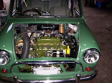
This blog, in addition to the usual maintenance details for classic mini cars, an attempt is made to explain the "whys" and "wherefores" of the various jobs.

Saturday, 17 October 2009

Descaling and Flushing Cooling System

At least once a year preferably in the autumn and in the spring if an anti-freezing compound is used the system should be drained, flushed-out and refilled. If the water does not flow freely from the radiator drain tap and from the tap on the side of the engine cylinder Wock (both are accessible from inside the engine compartment) the openings should be probed with a piece of wire to dislodge any accumulated sediment or better still, unscrew and remove the taps. A hose should then be inserted in the filler neck and water allowed to flow through the system until clean water issues from the taps.

Before flushing the system it is an advantage to run the car for a day or two with a proprietary non-corrosive compound added to the cooling water. These compounds will remove any deposits of rust or scale which might be sealing minor leaks. If anti-freezing compound is used without descaling the system, there is a risk that its very "searching" action may find such weak spots, with possibly serious consequences if a leak should develop and continue undetected during the course of a lengthy run.

If an interior heater is fitted and the cooling system has been drained, make sure that the heater water-control tap is open when refilling the radiator. It is a good plan to slacken the clamp on the radiator end of the heater hose when a recirculatory type of heater is fitted, and to loosen the hose in order to dispel any air-lock, that may develop in the heater. Do


The "anti-smog" crankcase ventilation valve ,1tted to some models. The valve should be cleaned with methylated spirits at 12,000-mile intervals


1. Spring clip
2. Cover
3. Diaphragm
4. Spring
5. Control orifice

not tighten the clamp until water is flowing from this point and re-check the level in the header tank after the engine has been running for a few minutes.

Transmission Couplings

The universal joints at each end of the two drive shafts should be checked during the 6,000-mile service. The rubber couplings at the inner end of the shaft may fail within 5,000-6,000 miles if oil is allowed to leak on to them, but can have a life of upwards of 30,000 miles if they are kept free from oil and the U-bolts are correctly tensioned. The self-locking nuts on the U-bolts should be tightened until two threads protrude. If they have been too slack or too tight for any length of time, the rubber cross-pieces in the couplings will have been damaged and should be renewed. It is as well to renew the self-locking nuts at the same time, and as the new bolts are quite cheap, it will do no harm to replace these also.


Faults in the couplings will cause knocks or vibration when starting from a standstill or when the wheels are turned towards full lock. The outer joints, which are of the mechanical type, can develop a knock when wear begins to develop, but provided that it occurs only towards full lock,it is usually safe to assume that the joints will still have a good deal of useful life left in them. Make sure, however, that the rubber boots over the mechanical joints and the splined connexions are in sound condition. It is not difficult to fit new boots after uncoupling the U-bolts on the rubber joint but it is essential to pack the splines and joints with the correct grease. For the mechanical joints, use only Duckham's Molybentone grease, B.M.C. Part No. AKF1457. The only grease approved for the sliding splines is Duckham's Lammol grease, Part No. 97H2611.


This cooling system thermostat is in good condition. The water-control valve (1) is closed and the bellows (2) undamaged


Checking and Adjusting the Brakes

Although any major shortcomings in the braking system will, of course, have been evident during the course of normal running, slight but progressive deterioration in braking efficiency inevitably takes place as the linings wear, the process being so gradual that it usually goes undetected by a driver who becomes familiar with the car and subconsciously adjusts himself to changes in its running. A critical reassessment of the braking efficiency at 6,000-mile intervals, therefore, is a useful check on this subconscious readjustment of values. As a number of factors affect braking efficiency, the testing and adjustment are dealt with in some detail in Chapter 10.

The Carburettor and Fuel System

The simple S.U. carburettor fitted to these cars requires very little attention. Owing to the large diameter of the jet and fuel passages, combined with the constant movement of the jet metering needle, troubles due to the jet being blocked by small globules of water or particles of sediment are virtually unknown.


The checks at this mileage, therefore, are confined to making sure that the idling mixture strength is correct, as described in Chapter 6, and examining the carburettor and the fuel pipeline and unions for any signs of petrol leakage. If necessary, tighten any clamping screws, but not to such an extent that the clamps are distorted.

If there are any symptoms of incorrect carburation, or leakage of fuel from the carburettor itself, the checks and adjustments described in Chapter 6 should be carried out.

The fuel pump normally requires no attention at this mileage which is perhaps just as well, as it is located rather inaccessibly on the inside of the left-hand rear side-member of the sub-frame and can be reached only when the car is over a pit or raised on "a hoist, or with the rear wheels supported on wheel ramps. However, pumps are not infallible and the servicing of this component is described in Chapter 6.

Valve Clearance Adjustment

If a small, highly-efficient overhead-valve engine is to be kept in good tune it is essential to check the valve clear¬ances at 6,000-mile intervals. The clearance between the tips of the inlet and exhaust valves and the rockers, when the valve is closed and the tappet is on the base of the cam, should be 0-012 in. (12 thousandths of an inch), measured when the engine is cold. It will be necessary, of course, to remove the valve cover.

To make sure that each tappet is on the base of the cam, adjust No. 1 rocker with No. 8 valve (counting from the fan end of the engine) fully open—that is, with the spring fully compressed—No. 3 with No. 6 fully open and continue in this manner by selecting pairs of valves that add up to 9. To take one further example, No. 7 valve would be adjusted with No. 2 fully open.

As a starting handle is not provided, the most convenient method of rotating the engine is to remove the sparking plugs and pull on the fan belt. This enables the correct position of the camshaft to be obtained more easily than the alternative method of engaging top gear and pushing the car backwards and forwards to rotate the engine.

To adjust the clearance, slacken off the adjusting screw lock-nut at the opposite end of the rocker to the valve and insert a feeler blade between the toe of the rocker and the valve tip. The adjusting screw should now be turned with a screwdriver until the correct clearance is obtained and held in this position while the lock-nut is tightened. A firm pressure should be applied to the screwdriver in order to displace all but a thin film of oil from the cupped ends of the tappet and push-rod. A false


Adjusting the valve clearance: 1, slacken the lock-nut and rotate the adjusting screw; 2, check the gap between the rocker and the tip of the valve with a feeler gauge


clearance may otherwise be obtained. Tighten the lock-nut and re-check the clearance.
 

The action of tightening the lock-nut will usually be found to change the adjustment slightly, so that one or two attempts may be necessary before an accurate clearance is obtained. It is advisable to use two feeler gauges to check the adjustment—one0001 in. too large, which should not enter, and one 0-001 in. too small, which should enter easily.

Remember that if the cylinder-head nuts are tightened down, the clearances will be reduced.

Before replacing the valve rocker cover inspect the cover gasket. If there is any doubt regarding its condition it should be renewed. Make sure that the cover is seating evenly on the cylinder head and is located correctly before replacing the sealing washers and tightening the securing nuts evenly.

Adjusting Free Movement of Clutch Pedal

It is important that a small amount of free movement of the clutch pedal should exist before the pressure of the main clutch springs is felt. About £—


in. is sufficient, but as the friction linings of the clutch wear, the free movement (which, in fact, indicates that a slight clearance exists between the clutch withdrawal thrust race and the thrust ring) will decrease. When the clearance between the thrust ring and the race is taken up, the clutch will no longer be able to engage fully and clutch-slip will develop.
Adjustment is carried out at the stop-screw shown in Fig. 18. The correct clearance, which must be measured with a feeler gauge, depends on the type of clutch. The appropriate figures are given on page 144. If necessary, slacken the lock-nut and turn the head of the screw to give the correct clearance.

Check the Fan Belt Tension

The fan belt, which also drives the generator or dynamo, should be kept free from grease and should be correctly tensioned. There should be a free movement of one inch at the centre of the belt between the fan and generator pulleys. If the belt is too slack, it will slip; on the other hand, if it is too tightly adjusted, excessive wear will occur on the fan and generator bearings. It is a simple matter to adjust the tension by loosening the two upper mounting bolts on the


Clutch adjustment (standard-transmission models):
 1, pull the operating lever in the direction of the arrow;
 2, adjust the clearance generator and the clamping bolt on the strut, allowing the generator to be swung towards or away from the engine.


The only snag is that the bolt on the strut is rather inaccessible, but if yours is not one of those Minis which have non-detachable radiator grilles, the best plan is to remove the securing screws and take off the grille. The bolt in question is then easily accessible as are also the ignition distributor, dynamo and starter. The owner of a Riley Elf or a Wolseley Hornet scores in this respect, of course, as the grille rises with the bonnet.

To increase the tension on the belt, pull the generator outwards; do not use any leverage. After the mounting bolts have been tightened, re-check the free movement of the belt.

The belt must be kept free from grease or oil. If it develops a squeak or a whistle, dust it with French chalk or smear the edges with a little brake fluid.

Eventually the time will come when the limit of the available adjustment is reached and a new fan belt will be required. Fitting is not too difficult, provided that one of the fan blades is aligned with the recess provided in the radiator cowling, just below the water hose on the right-hand side, as viewed from inside the engine compartment. Sufficient clearance will then be available for the belt to pass between the blade and the flange of the cowling, one blade at a time.